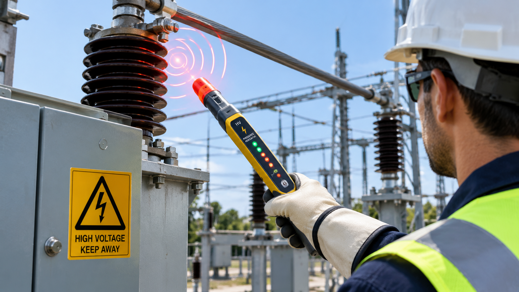
How Voltage Detection Supports Electrical Safety
A high voltage presence indicator helps operators identify energized electrical circuits in medium-voltage and high-voltage switchgear. It provides a visible indication of voltage presence through a sensing interface connected to energized conductors. This function supports safer operating decisions during routine inspections, switching operations, and maintenance preparation. Electrical distribution systems often contain multiple phases, enclosed busbars, and complex interlocking arrangements. Operators cannot determine electrical conditions through visual inspection alone. A voltage indication system provides an additional source of information without requiring direct contact with live components. However, its effectiveness depends on correct installation, suitable equipment compatibility, and reliable operation. Operators must also recognize the difference between voltage indication and verified electrical isolation. These distinctions matter because an indicator provides information about electrical conditions, rather than independently establishing that equipment is safe to touch.
What Is A High Voltage Presence Indicator?
A high voltage presence indicator is an electrical safety component that signals whether voltage exists at designated sensing points. Manufacturers commonly integrate these devices into medium-voltage switchgear, ring main units, and other enclosed distribution equipment. Their primary function involves displaying voltage presence for individual phases through indicator lamps or electronic displays. Many designs use capacitive coupling interfaces connected to sensing electrodes near energized conductors. These interfaces provide electrical signals without exposing operators to the conductors themselves. Some systems also support external voltage comparison or phase-concordance testing through compatible accessories. Nevertheless, indication capabilities vary between products, so operators should consult the manufacturer’s technical documentation. A voltage presence indicator does not automatically provide precise voltage measurements, identify every electrical fault, or confirm complete isolation throughout an entire installation.
How Does A High Voltage Presence Indicator Detect Live Voltage?
Many voltage presence indication systems operate through capacitive coupling between energized conductors and dedicated sensing electrodes. An alternating voltage creates an electric field around the conductor, which produces a corresponding electrical signal at the sensing interface. The coupling arrangement transfers a small signal without requiring a direct conductive connection to the high-voltage conductor. Depending on the design, the sensing interface connects to a dedicated indicator circuit through insulated wiring or integrated components. The circuit then evaluates the received signal against its specified operating threshold. When the signal meets the detection criteria, the corresponding indicator activates. Each phase typically has its own sensing path, allowing operators to identify phase-specific voltage presence. This process provides a practical indication of energized conditions, but its reliability depends on the complete sensing arrangement and the manufacturer’s specified operating characteristics.
Key Components Involved In Voltage Detection
Several components work together to convert electrical conditions into visible indications. Their design affects compatibility, sensitivity, and operational reliability. Examining each component’s function helps engineers assess installation requirements and troubleshoot potential indication problems.
Capacitive sensing interface: This interface connects the indicator system to designated sensing points associated with energized conductors. Its electrical characteristics influence the signal available to the detection circuit.
Signal transmission path: Dedicated conductors or integrated connections carry the sensing signal to the indicator electronics. Poor connections, incorrect wiring, or incompatible interfaces can compromise signal transmission.
Detection circuit: Electronic components process the incoming signal and compare it with the system’s operating threshold. Some designs include additional circuitry for self-monitoring or diagnostic functions.
Display element: LEDs or LCD modules communicate the detected condition to operators. Individual phase indicators help distinguish the electrical status of separate conductors.
Insulation and enclosure: Insulating materials, clearances, and protective housings support electrical separation and environmental durability. Engineers must evaluate these features against the equipment’s voltage rating and installation conditions.
Together, these components form a coordinated detection system. A suitable display cannot compensate for an incompatible sensing interface, and reliable electronics cannot overcome every installation defect. Equipment selection should therefore consider the complete interface rather than the display module alone.
How Different Voltage Conditions Affect The Indicator
Voltage indication depends on the electrical signal reaching the sensing circuit and satisfying its detection criteria. When a phase remains energized under the intended operating conditions, its corresponding indicator generally activates. A de-energized phase may produce no indication, provided the sensing interface and indicator operate correctly. However, an extinguished lamp does not necessarily prove that the conductor has reached a safe voltage level. Incorrect wiring, damaged components, incompatible sensing interfaces, or abnormal electrical conditions can affect the result. Residual voltage and induced voltage may also complicate assessments in certain installations. Operators should evaluate each phase separately instead of assuming that one illuminated or extinguished indicator represents the entire switchgear assembly. They must follow approved verification procedures before maintenance, especially when equipment contains multiple supplies, interconnected circuits, or possible backfeed paths.
Common Indicator Technologies And Their Differences
Voltage presence indication products use different display technologies and electronic arrangements to communicate electrical conditions. LED-based devices typically provide straightforward visual signals, while LCD products can present more detailed information depending on their design. Some systems incorporate additional diagnostic features or interfaces for phase comparison. These functions are not universal, so engineers should verify the actual specifications before selecting a product.
The following list summarizes common differences between available designs:
- LED indicators: Provide clear, simple visual signals for individual phases and generally suit applications requiring basic voltage presence indication.
- LCD displays: Can present phase-specific status or additional information when the product supports those functions.
- Diagnostic systems: May incorporate monitoring features that help identify selected device or connection problems.
- Phase comparison interfaces: Support phase-concordance checks when compatible equipment and approved procedures are available.
Display technology alone does not establish detection accuracy or safety performance. Engineers should compare operating thresholds, sensing interfaces, environmental ratings, and applicable verification requirements. They should also confirm whether the selected product supports the required nominal voltage range and installation configuration.
What Factors Affect Detection Accuracy And Reliability?
Reliable indication depends on the relationship between the sensing interface, electrical installation, and indicator electronics. A device designed for one interface configuration may not function correctly when connected to a different capacitive coupling arrangement. Engineers should verify rated voltage, interface compatibility, wiring diagrams, and manufacturer-defined operating thresholds before commissioning. Grounding arrangements and insulation conditions also affect the electrical environment surrounding the sensing system. Damaged insulation, loose connections, moisture, contamination, and component deterioration can compromise reliable operation. Temperature and other environmental conditions may influence performance when they exceed the specified operating range. Routine inspections should follow the manufacturer’s maintenance instructions and applicable electrical safety procedures. Where the design supports functional testing, technicians should use approved test methods and compatible equipment. They should never assume that a successful visual check alone confirms every part of the detection circuit operates correctly.
How Should Operators Interpret Voltage Indication Results?
Operators should treat the indicator as one source of electrical status information within a broader safety process. Its signals can support operational decisions, but they cannot replace prescribed isolation and verification procedures. Before interpreting the display, personnel should confirm that the device matches the switchgear’s sensing arrangement and that its phase labels correspond to the actual installation. They should also check for visible damage and follow the manufacturer’s instructions for functional verification.
Important checks include:
- Confirm the device’s compatibility with the installed capacitive sensing interface.
- Check phase identification and wiring against approved electrical drawings.
- Inspect the display and connections for visible damage or deterioration.
- Interpret each phase indication according to the manufacturer’s specifications.
- Investigate unexpected indications through approved diagnostic procedures.
- Follow established isolation, lockout, and absence-of-voltage verification requirements before maintenance.
These checks reduce the risk of misinterpreting an indication or overlooking an installation problem. An illuminated indicator generally signals detected voltage at its designated sensing point. An extinguished indicator, however, does not independently establish that the circuit is de-energized. Qualified personnel must use appropriately rated test equipment and approved procedures to verify electrical safety.
Why System Compatibility Matters During Equipment Selection
Selecting a suitable indicator requires more than matching the switchgear’s nominal voltage rating. Engineers must verify the capacitive interface type, connection arrangement, phase configuration, and intended indication functions. They should also consider the available mounting space, environmental conditions, display visibility, and maintenance requirements. For replacement projects, the original product’s dimensions and connector arrangement may influence mechanical compatibility. Electrical compatibility remains equally important because different interfaces can produce different signal characteristics. Procurement teams should request manufacturer documentation covering the operating principle, technical ratings, installation requirements, and testing procedures. Where projects require additional diagnostic functions, engineers should confirm that the complete system supports those functions. Careful specification helps prevent installation mismatches and supports dependable operation throughout the equipment’s service life.
Conclusion: Integrating Voltage Indication Into Electrical Safety
Voltage presence indication systems use electrical sensing interfaces and electronic circuits to communicate whether designated conductors appear energized. Capacitive coupling allows many designs to detect voltage without direct conductive contact with the high-voltage conductor. The display then converts the detected signal into a visual status that operators can interpret. Reliable performance depends on compatible interfaces, correct wiring, suitable environmental conditions, and appropriate maintenance. Engineers should evaluate the complete system rather than choosing equipment solely by display type or nominal voltage. Operators must also recognize the limitations of voltage indication during switching and maintenance activities. Approved isolation procedures and suitable absence-of-voltage testing remain essential before personnel work on electrical equipment. When correctly specified and integrated, a high voltage presence indicator provides valuable information for switchgear operation and electrical safety management.
Frequently Asked Questions
Can A High Voltage Presence Indicator Measure The Exact Voltage?
Most voltage presence indicators primarily identify whether a designated sensing point meets the device’s voltage detection criteria. They do not necessarily measure voltage accurately enough to provide a numerical reading. Their sensing circuits typically evaluate an electrical signal against specified operating thresholds. Some advanced products may provide additional voltage-related information, but their capabilities depend on the particular design. Engineers should consult the manufacturer’s technical documentation to determine whether a product supports quantitative measurement. When precise voltage readings are necessary, qualified personnel should use appropriately rated measuring instruments designed for the intended electrical system. They must follow applicable safety procedures and instrument instructions. A presence indication and a calibrated voltage measurement serve different purposes, so one should not automatically replace the other.
Can A Voltage Presence Indicator Work Without Direct Contact With Live Conductors?
Yes, many systems detect voltage through capacitive coupling rather than direct conductive contact with an energized conductor. The conductor’s alternating electric field produces a signal at a dedicated sensing interface. That interface transfers the signal to an indicator circuit, which evaluates the input and activates the corresponding display when its operating criteria are met. This arrangement supports enclosed switchgear designs because operators can receive an indication without touching exposed live parts. However, the system still requires a suitable sensing interface and correct electrical connections. Not every indicator uses an identical sensing method, and performance depends on the manufacturer’s design. Installation teams should follow the specified wiring diagrams and verify compatibility before commissioning the equipment.
Does An Extinguished Indicator Mean That Switchgear Is Safe To Maintain?
No. An extinguished indicator alone does not establish that switchgear is safe to maintain. The display may remain inactive because the circuit is de-energized, but equipment faults, wiring problems, or incompatible sensing components can also affect its response. Additional hazards may arise from alternate supplies, induced voltages, stored electrical energy, or interconnected circuits. Qualified personnel must follow the applicable isolation procedure and secure the equipment against unexpected re-energization. They must then verify the absence of voltage using appropriately rated test equipment and approved methods. Any additional grounding or protective measures required by the installation must also be applied. The indicator provides useful supporting information, but it cannot replace formal electrical safety procedures.

 Welcome to CreativeGeneralist.com, your premier destination for authentic news, captivating stories, and insightful posts curated from across the globe. We meticulously select diverse content to inform, entertain, and inspire.